
Sep 5, 2026Product Knowledge & Guides
Modular Building Installation Guide: Site Preparation to Handover
A practical installation guide for contractors and project buyers covering foundations, delivery, lifting, module connections, utilities, inspections and handover.
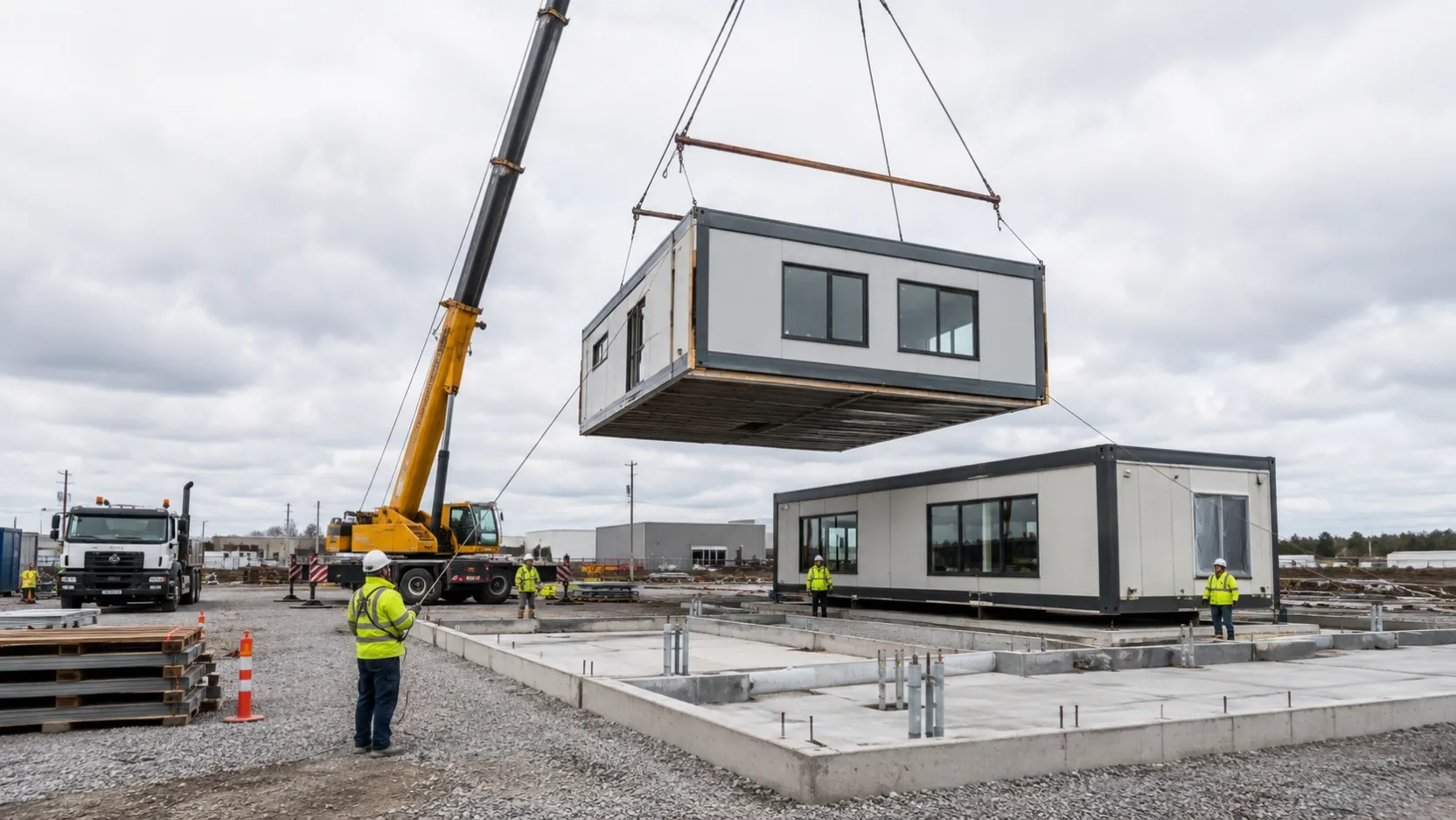
Modular building installation is the point where factory work, shipping, foundations and local construction meet. A well-made module can still arrive to an unprepared site. A perfect foundation can still sit idle because the delivery route or lifting plan was never checked. Most expensive installation problems begin before the truck reaches the gate.
This guide is written for contractors, project managers and procurement teams buying steel modular buildings for overseas projects. It explains the sequence from approved drawings to handover, while keeping one important distinction clear: opening a foldable unit, deploying a bi-wing expandable unit and setting a multi-module building are not the same operation.
Modular building installation at a glance
- Approve the general arrangement, foundation, service and connection drawings.
- Confirm the scope split between the manufacturer, buyer and local contractors.
- Complete and survey the foundation and underground services.
- Check the delivery route, unloading area and lifting or deployment equipment.
- Receive and inspect the modules in the required installation sequence.
- Position, open or lift each unit according to its system.
- Complete structural connections, anchoring and weatherproofing.
- Connect electrical, water, drainage and other building services.
- Inspect, test, commission and document the completed work.
The Modular Building Institute describes completed modules being transported to site, placed on their foundations and connected structurally before building services and finishes are completed. That broad sequence is consistent across many projects, but the details remain specific to the engineered building and local rules. See the institute’s overview of the modular building process.
First identify the building system
Foldable container house
A foldable unit arrives as a low packed structure. The site team unloads it, places it on the prepared support points, unfolds the wall and roof sections, aligns the frame, secures the structure and completes seals and service connections. The equipment and crew depend on unit weight, design and the supplier’s instructions.
Our listed standard foldable unit is 5,800 × 2,430 × 2,460 mm when deployed, with a folded width of 320 mm. This is useful for initial planning, but the approved project drawing and packing list govern the actual installation.
Bi-wing expandable container house
An expandable model arrives as a central body with two folded wings. It must be positioned with enough clear area on both sides. The wings are opened and supported, end walls and joints are secured, and the perimeter is checked before utility connections and interior finishing are completed.
Bathroom, kitchen and electrical packages can change the weight distribution and site connection points. The lifting and foundation plan must be based on the selected model, not a generic 20 ft or 40 ft description.
Multi-module or two-storey building
A connected or stacked building requires a coordinated setting sequence. Each module is placed according to its identification number, secured temporarily, aligned, connected to the foundation and adjacent modules, then weatherproofed. Stairs, corridors, roofs, external cladding and service interfaces may involve additional site work.
Multi-storey work requires project-specific structural engineering, temporary stability provisions, fall protection and an approved lifting method. Do not extend the installation instructions for a single foldable unit to a two-storey building.
Documents to close before shipment
Modular building installation planning should begin while the modules are still in production. At minimum, the project team should agree on the following documents:
- approved general arrangement and room schedule;
- foundation loads, support points and anchor details;
- module dimensions, weights and centres of gravity where required;
- lifting points, spreader requirements and handling restrictions;
- module-to-module connection details;
- electrical, water, drainage and data interface drawings;
- packing list and delivery sequence;
- installation manual and inspection records;
- responsibility matrix and exclusions;
- local permits, inspections and acceptance requirements.
A drawing marked “for quotation” is not an installation drawing. The buyer should make sure the issue status, revision and approval record are visible on the documents used by the site team.
Define who is responsible for each interface
Work item | Typical lead party | What must be agreed |
|---|---|---|
Module design and factory production | Manufacturer | Approved specification, drawings and quality records |
Local structural review and permits | Buyer/local professional team | Applicable code, submissions and approvals |
Foundations and underground services | Local civil contractor | Set-out, levels, cure status and interface locations |
Transport and delivery permits | Logistics provider/buyer | Route, vehicle, escort, timing and site access |
Crane, forklift and rigging | Qualified local lifting contractor | Capacity, radius, ground bearing, lift plan and weather limits |
Module placement and connections | Installation contractor | Sequence, temporary stability, tolerances and records |
Utility tie-ins | Licensed local trades | Connection points, testing and certification |
Final inspection and handover | Buyer/AHJ/project team | Acceptance criteria, defects and documentation |
This table is a starting point. Contract scope and local law determine the final responsibilities.
Prepare the site and foundation
Survey and set-out
Build the foundation from the approved module support drawing, not only from an architectural floor plan. Check the building grid, diagonals, support elevations, anchor locations and service penetrations before concrete is poured. Survey them again after completion.
Small errors become expensive when a finished module is waiting on a truck and the booked crane is charging by the hour. The acceptable tolerance must come from the project engineer and the module connection design.
Ground, drainage and foundation type
Foundation selection depends on soil, building loads, intended duration, frost, drainage, wind and local requirements. Options may include pads, strip footings, slabs or engineered pile systems. The building should not be placed on an improvised support arrangement because a similar-looking project used one.
Grade the site so water does not collect beneath the building. Plan inspection access where services or adjustable supports remain below the floor.
Utility interfaces
Complete underground drainage, water, electrical conduits and other buried work before modules block access. Mark every connection point and compare it with the current service drawings. Protect open pipes and conduits from concrete, dirt and transport damage.
Delivery route and laydown area
Walk the route from the public road to the final module position. Check gate width, turning radius, slopes, overhead lines, trees, soft ground and the ability of vehicles to leave after unloading. A site may be accessible to a small truck but not to a long loaded trailer.
Provide a level laydown area if units cannot move directly from the truck to their final positions. Define safe pedestrian routes and keep unrelated work away from unloading and lifting zones.
Plan the crane, forklift or deployment equipment
Equipment selection is an engineered and site-specific decision. Module weight is only one input. The lifting contractor also needs the required radius, boom configuration, rigging weight, ground conditions, wind limits and obstacles around the lift path.
Where a crane is used, the lift plan should address the sequence, crane position, outrigger or track support, exclusion zones, lifting accessories, communications, emergency arrangements and the point at which each module becomes stable. In the United States, crane activity may fall under OSHA construction requirements, including rules for work near power lines. Buyers should verify the rules that apply at their own location; the official GovInfo record for 29 CFR 1926.1408 power-line safety requirements is one example of the controls that can affect a lift.
The manufacturer should provide verified handling information. The local qualified lifting team remains responsible for choosing and operating equipment under site conditions.
Receive and inspect the modules
Match each arriving unit to the packing list and installation sequence. Record the module number, transport condition and any visible damage before unloading. Pay particular attention to:
- frame distortion or impact marks;
- panel edges, roof membranes and flashing;
- doors, windows and glazing;
- lifting points and transport restraints;
- loose furniture or internal equipment;
- service tails and protected connections;
- seal kits, fasteners and loose accessories.
Photograph any issue and agree on the next action before the damage is hidden by installation.
Set or deploy the building
Conduct a pre-work briefing
Review the module identification, sequence, drawings, weather, communications, exclusion area and stop-work conditions. Confirm that the crew understands who directs the operation.
Position the first unit carefully
The first unit establishes the line and level for everything that follows. Check it against the surveyed grid before final anchoring. On multi-module work, errors in the first placement accumulate at later joints.
Secure before releasing lifting equipment
Do not release rigging or remove temporary supports until the module has reached the stability condition defined by the engineer and installation method. The same principle applies to foldable and expandable systems: opened panels and wings must be locked and supported in the specified sequence.
Continue in the approved order
Place modules so that the crane or handling equipment retains access and completed work does not block later units. Keep fasteners, seals and connection tools available at the point of work rather than in a separate delivery.
Complete structural connections and weatherproofing
Connect the modules to the foundation and to one another using the specified fasteners, plates or brackets. Record required inspections and bolt checks. Substituting a similar fastener without approval can change the connection capacity and corrosion performance.
Close the building envelope as early as practical. Complete roof joints, wall junctions, corner trims, flashing and sealants in the specified order. Temporary protection may be needed if permanent work cannot be finished on the day of placement.
Inspect fold lines, expandable-wing junctions and service penetrations. A fast installation that traps water inside a joint is not a successful installation.
Connect services and finish the interfaces
Licensed local trades should complete and test the building services required by the project. Typical work includes:
- connecting incoming electrical supply and bonding;
- joining electrical circuits between modules;
- connecting water, drainage and vent systems;
- installing or commissioning HVAC equipment;
- connecting fire alarms, sprinklers or other life-safety systems where required;
- finishing floors, walls and ceilings at module joints;
- installing stairs, ramps, decks, skirting or canopies.
Factory-installed work and field-installed work should be tested together as one building.
Inspect, commission and hand over
Create a close-out list by discipline. Check structural connections, alignment, doors and windows, weather seals, roof drainage, electrical systems, water pressure, drainage, HVAC operation and interior finish. Record defects, responsible parties and completion dates.
The handover package may include approved drawings, material records, factory inspection reports, site inspection records, test certificates, equipment manuals, spare-parts lists, maintenance instructions and photographs of concealed connections. The required package should be agreed before production, not assembled as an afterthought.
Common installation failures
- Foundation set-out does not match the module drawings. Survey before shipment and before equipment is mobilized.
- Service connections are in the wrong position. Coordinate factory and local drawings through one controlled revision process.
- The truck reaches the site but cannot reach the unloading point. Complete a route and turning review.
- The crane cannot achieve the required capacity at radius. Provide verified weights and a scaled site plan early.
- No one owns the work between the modules. Use a written scope matrix.
- Joints remain exposed after placement. Plan temporary and permanent weather protection.
- The crew uses a generic online video instead of the project manual. Brief the team on the approved drawings and installation method.
Information needed for an installation proposal
To prepare a practical modular building installation scope, provide the building system, model, quantity, site country, site plan, foundation status, access conditions, available equipment, utility arrangements, local design criteria and target handover date.
For product-specific information, review our foldable container house, bi-wing expandable house and two-storey modular building. For a project-based installation scope, send the site and delivery details.
This guide provides general planning information. Final foundations, lifting operations, structural connections, services and approvals must be designed and carried out by qualified parties under the requirements applicable at the project location.